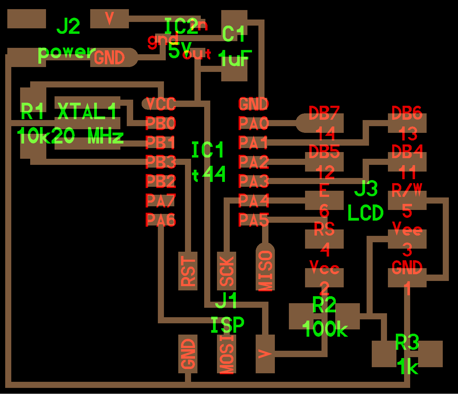
For this assignment we have to add an output device to a microcontroller and program it to do something. In this case I chose to work with the LCD to which we will consider the following processes.
|
| |
LCD board |
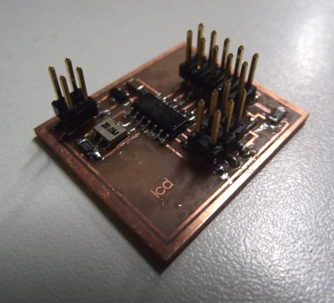
Milling and welding components |
|
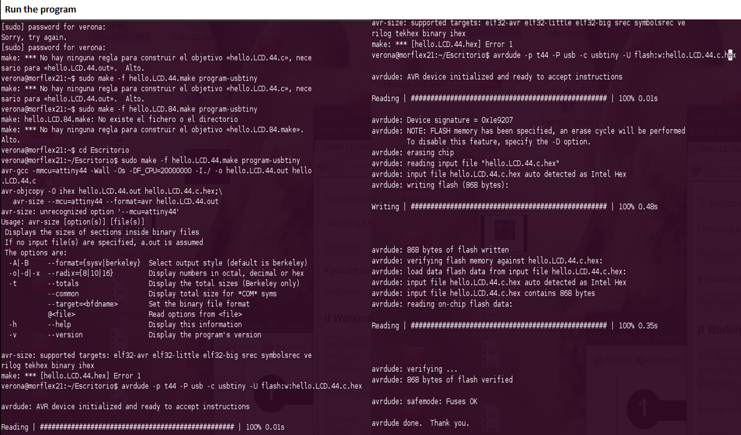
Program (with Fab ISP) and run the board
|
| |
|
|
|
 |
| |
|
|
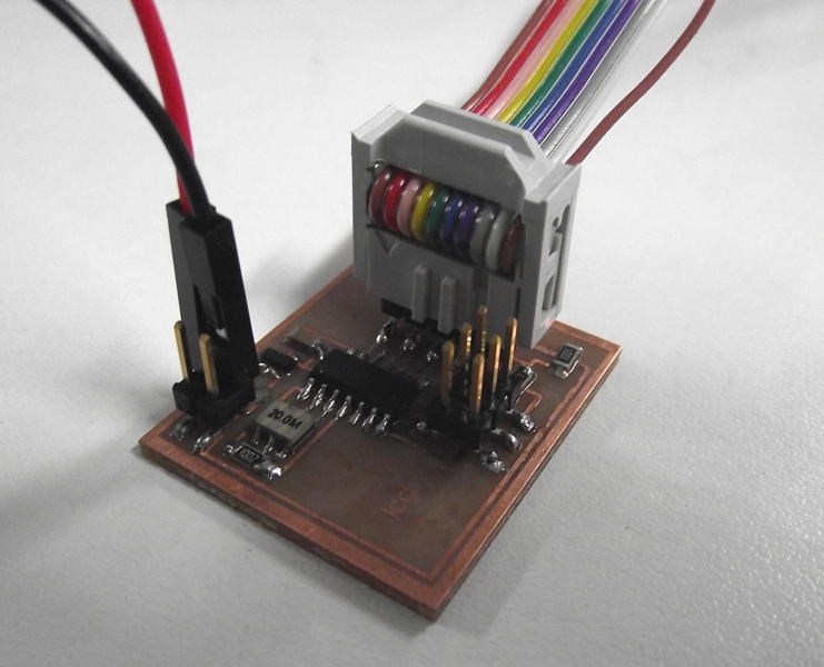
When we finished to welding our board, we check the polarity of the power supply (230V) also made sure the conecctions with hot glue. In the case of the Arduino board, we identified the pins, and then make the respective connections (wiring diagram).
|
Materials and tools:
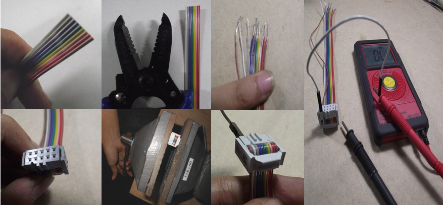
* Wire rabbon cable (in our case we only had a 9-conductor cable, sowe had to add aditional cable to complete the 10-pin) and stripping wires.
* Wire strepper
* Vise squeez
* Multimeter
Clamp the assembly in a vise and squeeze it (by tightening the vise) until you hear two faint clicks indicating that the connections are made between the connector and the wire.
|
 |
|
|
|
|
 |
|
Text editing with ARV Studio : "Life will surprise you: smile ... "
|
Final Comments: This asignment I learned about several output devices such as LED array, LED RGB, LCD and Sonar. I would like to continue to work with other devices such as motors
|
| |
